Friction Disks
Udo Schweizer’s Texturing Pages
| Friction disks insert the necessary false twist into the running yarn, so that the yarn can get textured. The disks are commercially available from a large number of vendors such as machinery suppliers and ceramics producers. The disks will have to conform to a set of design specifications depending on the machine, respectively the friction unit manufacturer. They are not always interchangeable. Specifications, which are important to observe are: outside diameter, inner diameter and thickness. |

Friction units have been around for many years and the design characteristics have changed over the years. In earlier times, when friction texturing machines ran slower, the thickness used to be 4-6 mm. Today, most modern high speed processes are running on 9 mm thickness disks.
Friction disks are expensive, precision made parts. The assembly of disks in a friction unit must be accordingly accurate. The disks are separated by spacers to obtain an exact disk spacing, normally 0.5 mm. Exemptions, such as 0.6- 0.75 mm were made for special needs. Because disks rotate at high speeds there must be absolutely no interference or touching of the disks, as this will create a high amount of frictional heat, which destroys the expensive disks and can pose, consequently, a real danger to the machine operator.
Working Disks
Friction Disk Materials
We differentiate between hard and soft disks. Hard disks are either metal or ceramic based, soft disks are normally of a plastic/polyurethane construction. Ceramic or polyurethane (PU) are the materials in touch with the yarn.
Metal Disks
The base material is normally aluminum. The friction surface is coated with a material, which transmits enough friction to the yarn without hopefully abrading the yarn too much. Known coatings are plasma, powder vapor deposition, aluminum oxide nano deposition and diamond coatings. Although tough and durable, I have found these coatings to change over time. In addition, plasma coated surfaces can be damaged easily.
Ceramic Disks
These disks are normally made of an Al2O 3 ceramic. They are extremely hard, durable and have a surface, which has proven to change little over time. The hardness of the disks presented in the past the disadvantage that the disks were quite abrasive, causing a large amount of polymer/spin finish dust (snow) to accumulate on the machine. This was a continuous housekeeping challenge. The latest generation of ceramic disks have vastly improved surfaces, which still insert enough twist, but reduce the amount of fiber abrasion significantly. In recent tests I have found them to be very close to PU disks.
PU (Polyurethane) Disks
They offer a much higher amount of friction and therefore more twist. As synthetic fibers are normally harder than PU, there is no noticeable fiber abrasion. This results in improvements regarding tenacity and elongation of the textured yarn. But the softness of the disk also means that its lifetime is limited. This can become a commercial issue. Good disks can last, depending on spin finish, ambient air temperature, denier and yarn speed, up to 12 months. But even longer lifetimes have been reported. The PU Shore hardnesses available are 86 and 90 ° Shore A.
Rubber Disks
Some years ago I could see some rubber disks exhibited. They were then being tested by a texturing machinery producer. It appears now that such disks cannot offer a sustainable advantage over PU disks.
Friction Disk Arrangements
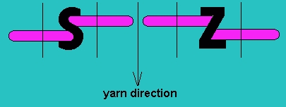
For S and Z twist the disks are stacked differently. The following illustration is an easy reminder how the disks have to be stacked in order to obtain S or Z twist.

Entry and Exit Disks
The main function of the entry and exit disk is to make sure that the yarn is fully in touch with the top and bottom working disk. This way the full twist potential of the working disks can be exploited. Usually the disks are highly polished, which means minimum torque and twist loss. Frequently the exit disk has a distinctive edge. It was developed to counter tight spots in the yarn. When PU disk are being used the use of ceramic entry and exit disks is nearly mandatory. The ceramic disks protect the soft PU disks against operator errors during the string up of the yarn.
Yarn Path through the Friction Unit
All commercial friction disk units consist of three shafts on which the overlapping disks are being stacked. The yarn travels in a three dimensional helix from disk to disk. The number of working disks is determined by the processing parameters, such as denier, yarn speed and twist level. A typical setup for 150/48 den is a 1-7-1 configuration for hard disks and a 1-4-1 configuration for soft disks. (1-7-1 means one entry disk, 7 working disks, 1 exit disk)

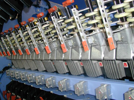
Motorized friction units on a HY2-V texturing machine, below on-line tension measurement devices
D/Y Ratio
The disk surface speed vs. the yarn speed (D/Y) is adjusted to a desired T2/T1 tension ratio. T1 is the tension at the entry of the unit and T2 the exit tension. D/Y ratio is one of the critical process parameters. If the D/Y is too low the T2 tension would be too high and the T1 tension too low. This can lead to an unstable texturing process. Faster turning disks increase the T1 tension slightly but markedly lower the T2 tension. Processes run successfully even with reversed tension ratios, T2/T1
Disk Design
All disk designs are based on years of experience and research. Special attention has been given to the curvature of the working surface. Today there are two profiles available, the round (C-profile) and the D-profile. The round profile consists of one singe radius, e.g. 6.5 mm for a 9 mm thick disk. The D-profile has two individual radii, e.g. 3.5 mm for the edge radius and 9.5 mm for the radius on the working surface. The round profile is used more often, although the D-profile has shown to also give good results.

Yarn transport through the friction unit
In order to understand the twisting and feeding action of a friction unit the basic design of the unit must be understood. Talented engineers have for the last 25 years honed their skills in creating friction units, which will insert an optimum amount of twist. At the same time the unit will also positively push the yarn through the unit. This twist and push is achieved by having the yarn run at an angle over the surface. The following drawing will help to better understand this action:

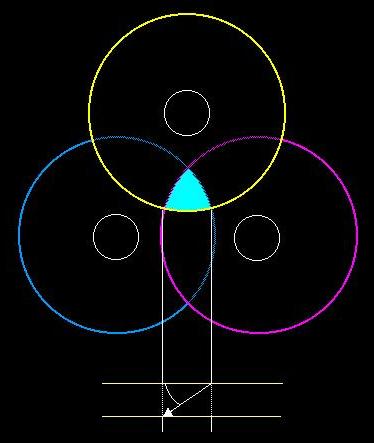
Depicted here are three 52 mm diameter disks arranged on shafts with a shaft distance of 37 mm. The yellow disk is the top disk, next the red and then the blue disk. Normally 6-9 disks are stacked like this together. The disks overlap and the yarn will run along the surface of the disks on the periphery of the highlighted area in the center. The vertical distance is 0.5 mm between adjoining disks.
Projected below is the yarn path on the yellow disk. The yarn will be in contact with the disk along the indicated length. The two horizontal lines on the bottom indicate the 9 mm thickness of the disk. The arrow indicates the yarn path. Important for the twist insertion is the angle of the yarn path over the disk. The steeper the angle, the more twist will be inserted. The smaller the angle, the more the yarn will be pushed along the surface of the disk, which effectively reduces the yarn tension below the friction unit. By choosing the correct angle a compromise is found, where the yarn is twisted sufficiently for good texture and, due to the pushing action, at relatively low yarn tensions.
The industry optimizes processes by selecting the number of disks and in rare cases the diameter and hardness of the disks. Very slightly increased disk diameters will lead to a smaller contact angle of the yarn, thus a lower twist level coupled with low post spindle tension. In some cases, this technique is used to reach higher process speeds.
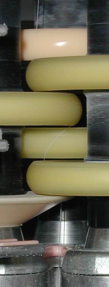
Here is a picture of a yarn running at 1000 m/min S-twist on a friction unit, which is stacked 1-4-1. The four working disks and the ceramic entry and exit disk can be clearly identified. The yarn direction is from the top to the bottom.

The yarn enters, nearly perpendicular, at the ceramic entry disk. From there it moves in a three dimensional fashion over the polyurethane working disks. The path over the third working disk from the top is visible. As indicated in the drawing above, the yarn runs at a certain angle over the disk. In reality this is a very dynamic process, where there cannot be a straight line. As can be observed, the yarn curves around the disk. At the top of the disk the angle is lower, pushing the yarn more, which reduces the tension below. The maximum amount of twist is inserted in the area, where the angle is steeper and the contact is closer to perpendicular.
The D/Y ratio is normally around 1.7-1.8. That means that the disk surface speed is 1.7 – 1.8 times faster than the linear yarn speed. This speed is a fair amount higher than the rolling speed of the highly twisted yarn bundle. Thus the yarn is constantly driven by faster moving surface. Wear of PU disks can be attributed to this fact. The same can be said for ceramic, where the fast moving and extremely hard ceramic surface constantly abrades the much softer yarn. This leaves a fine powder, called snow, on the machine.
The bottom disk in this picture is a so-called knife-edge disk, which can be found on many texturing machines. It supposedly helps to eliminate tight spots. It has a polished edge with a very small radius. This disk can be made of either of a very special wear resistant metal or of ceramic.
- Educational Texturing Pages
